Implementation
(a) Describe any hardware you used or built. Illustrate with pictures and diagrams.
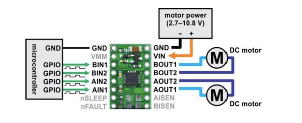
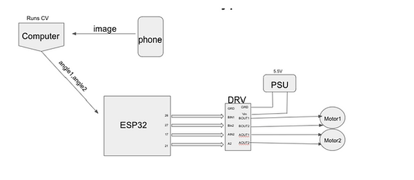
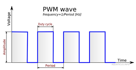
The hardware of our project consisted of three main components: ESP32, DRV8833, and two DC motors. The ESP32 microcontroller acted as the brain of our hardware. By connecting to the internet and subscribing to an MQTT topic, the ESP32 allowed us to communicate with our hardware remotely and trigger the motors to reach our desired turn. The DRV8833 is a premade circuit used for controlling DC motors. In our project the DRV acted as a middleman between the ESP32 and the two DC motors, by enabling us to trigger the motors using PWM signals from the microcontroller, but powering the motors using an external 5.5 V battery. We didn’t power the motors directly using the ESP32 because it wasn’t able to supply a voltage high enough to turn the motors, and also powering the motors directly could damage the ESP32. The last component was a set of two 3-6 V DC motors which we attached to knobs to turn them.
(b) What parts did you use to build your solution?
To build our solution, we used the aforementioned hardware along with several software components. We used MQTT as a messaging system between our microcontroller and remote machine. Specifically, we used the Paho Python MQTT library in order to construct MQTT messages in Python. We used the OpenCV library to perform all computer vision functionality. Finally, we used the PyQT library to construct the GUI of our remote application.
(c) Describe any software you wrote in detail. Illustrate with diagrams, flow charts, and/or other appropriate visuals. This includes launch files, URDFs, etc.
Software Architecture
Computer Vision
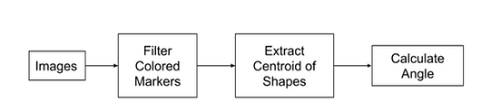
Our OpenCV code analyzes two images. One is the “Base” image depicting the “off” position and the other is the “Rotated” image depicting the “on” position. We will walk through our code, focusing on the blue marker as the example.

Our OpenCV will receive an image as seen above and begin the color filtering process. The first step is identifying the BGR (Blue-Green-Red) values of each non-white marker on the stove knob. It should be noted that we extracted the values manually but the final product will most likely have a set color beforehand. We then convert the BGR color to HSV (Hue-Saturation-Value) because the filter function uses HSV.

To get an accurate filter reading, we will define a lower and upper bound on the color blue and use it to create the mask.


We then apply a bitwise AND function to the image and the blue mask. The resulting image is seen below.

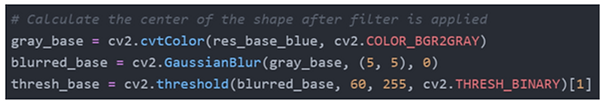
Using the Filtered Base Blue image found above, we will find the centroid of the marker. First we convert the image to a grayscale, then we convert the grayscale to a binary image, and lastly, we calculate the centroid of the shapes found. Below are the lines of the first two conversions.
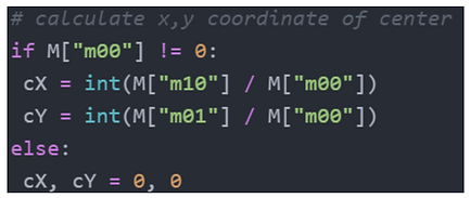
Then we identify the shapes of the markers to then calculate the centroid of the shape using Image moments.

Image Moment is a weighted average of image pixel intensities so we can calculate the x and y position of the centroid using the formula below.
Here is an output of applying these processes to both images:

I placed the points we found in the image in homogeneous coordinates. For example, the blue center points were inserted into an array in this form: [cX, cY, 1].

Since each knob is considered a zero-pitch twist, I used inverse kinematics to find the angle. In our example, base_pt refers to point p while rot_pt refers to point q in the image. Point r can be any point along the twist but as a 2D image, I chose to set it as the origin of the knob.
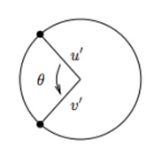
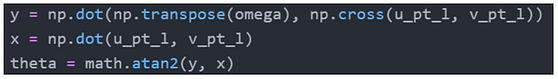
We defined ω = [0, 0, 1] in the positive z direction and found the u’ and v’ vectors for both the base and rotated center points. The code below is finding the vectors in the left knob of the images.

Using this formula:
We found the angle of rotation
Integration
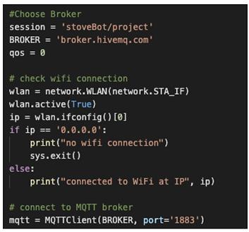
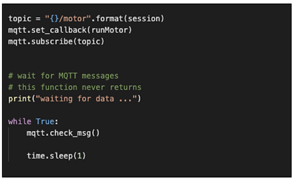
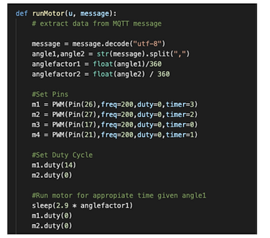
The microcontroller subscribes to the appropriate MQTT angle topic. Upon receiving a message triggering a callback function, the microcontroller decodes the message, calculates a specified length for which the DC motor should run, and generates appropriate PWM signals driven with a calibrated duty cycle such that the motor is set at an appropriate speed. The duration at which the PWM signal is generated allows for the knob to turn just the right amount to turn to the off state.
(d) How does your complete system work? Describe each step.

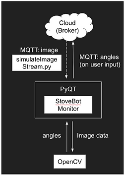
Overall System Architecture
Our software components are running on a remote machine, and are written using PyQT and OpenCV as its main libraries. The application receives an image stream (some image every n seconds) from the cloud, or MQTT broker as a raw jpg image, by subscribing to the relevant image topic. Realistically in a real-world system, this image data would come from a dedicated camera mounted to monitor the stove at all times, capturing image data every n seconds and publishing it to the MQTT topic. Because of constraints for this remote semester, we instead model this behavior without camera hardware with the simulateImageStream.py, which effectively mimics the behavior by publishing specified jpg images every n seconds. This is essentially sending an image from the microcontroller to the remote machine. Our application then processes the image via OpenCV (see CV section), which returns two angles at which the stove knobs in the image are turned to. Our application manages all this and updates the GUI implemented in PyQT asynchronously, such that it is able to receive image data, do OpenCV processing, and update the GUI at the same time. Our application does so by running our OpenCV processing on the image in a separate thread and making use of callback functions as well as the publisher/subscriber model of MQTT (similar to ROS) to pass data between our project components. Once a user notices a stove in the ON configuration, they are able to press a button to turn the stove off, which publishes the angle commands to the MQTT angle topic, where hardware will receive the angles, and effectively convert that angle into the duration to turn the DC motors to accurately turn the stove knobs into the off position.